Contraction/Control Joints
 Contraction/control joints are placed in concrete slabs to control random cracking. A fresh concrete mixture is a fluid, plastic mass that can be molded into virtually any shape, but as the material hardens there is a reduction in volume or shrinkage. When shrinkage is restrained by contact with supporting soils, granular fill, adjoining structures, or reinforcement within the concrete, tensile stresses develop within the concrete section. While concrete is very strong in compression the tensile strength is only 8 to 12 percent of the compressive strength. In effect, tensile stresses act against the weakest property of the concrete material. The result is cracking of the concrete.
There are two basic strategies to control cracking for good overall structural behavior. One method is to provide steel reinforcement in the slab which holds random cracks tightly. When cracks are held tightly or remain small, the aggregate particles on the faces of a crack interlock thus providing load transfer across the crack. It is important to recognize that using steel reinforcement in a concrete slab actually increases the potential for the occurrence of random hairline cracks in the exposed surface of the concrete.
The most widely used method to control random cracking in concrete slabs is to place contraction/control joints in the concrete surface at predetermined locations to create weakened planes where the concrete can crack in a straight line. This produces an aesthetically pleasing appearance since the crack takes place below the finished concrete surface. The concrete has still cracked which is normal behavior, but the absence of random cracks at the concrete surface gives the appearance of an un-cracked section.
Concrete slabs-on-ground have consistently performed very well when the following considerations are addressed. The soils or granular fill supporting the slab in service must be either undisturbed soil or well compacted. In addition, contraction joints should be placed to produce panels that are as square as possible and never exceeding a length to width ratio of 1.5 to 1 (Figure 1). Joints are commonly spaced at distances equal to 24 to 30 times the slab thickness. Joint spacing that is greater than 15 feet require the use of load transfer devices (dowels or diamond plates).
Figure 1a: Joint Spacing in Meters
Figure 1b: Joint Spacing in Feet
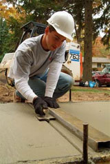
Contraction joints may be tooled into the concrete surface at the time of placement. Joints may be tooled into the surface (first pass) prior to the onset of bleeding or immediately with the first pass of the floating operation. The longer the first pass for jointing is delayed the more difficult it will be to shape clean straight line joints. Tooled joints should be re-established with each successive pass of finishing operations.
Joints may also be sawed into the hardened concrete surface. It is important to understand that the longer sawing is delayed the higher the potential for cracks to establish themselves before sawing is complete. This means that any cracks that occur before the concrete is sawed will render the sawed joint ineffective. Timing is very important. Joints should be sawed as soon as the concrete will withstand the energy of sawing without raveling or dislodging aggregate particles. For most concrete mixtures, this means sawing should be completed within the first six to 18 hours and never delayed more than 24 hours. Early-entry saws are available which may allow cutting to begin within a few hours after placement.
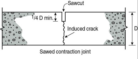
Contraction/control joints must be established to a depth of ¼ the slab thickness (Figure 2). Proper joint spacing and depth are essential to effective control of random cracking.

Figure 2: Minimum Depth of Contraction Joints